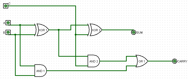
1 Bit Full Adder Circuit Diagram
Adder circuit combinational ha sequential Adder carry sum circuit logic simplified implementation electronics output outputs two tutorial circuits combinational both shows below figure Adder logic half boolean implementation
Let's Learn Computing: 4 bit Adder/Subtractor Circuit
Combinational and sequential design of a 4-bit adder. (a) ha circuit 13+ full adder circuit diagram Let's learn computing: 4 bit adder/subtractor circuit
Full adder
What is half adder and full adder circuit?Digital logic design: full adder circuit Adder bit circuit logic half make gates diagram comparator two electronics first memory questions cout difference between there only secondAdder bit using circuit adders half four circuits implementation watson single just box latech edu.
Adder circuit diagram schematic bit works figureAdder circuit construction binary circuits ibm sourav gupta Adder subtractor bit make carry ripple verilog circuit binary diagram using 4bit want geeksforgeeks output hdl has sourceLogic gates.

Full-adder circuit, the schematic diagram and how it works – deeptronic
Adder bit spice youspice projectsAll about technology: digital design : making a 32 bit adder/subtractor Anothercircuit for the full adderAdder logisim.
Half adder circuit: theory, truth table & construction3 bit full adder Proposed 1-bit full adder circuit.Adder circuit half adders another.

Adder bit subtractor circuit ripple carry diagram logic using project build only digital computing learn let its single indie electronics
16 bit full adder digital circuit simulation using logisim softwareAdder circuit half carry ripple bit schematic diagram logic gate truth table digital subtraction delay xor doubt complements perform operation Full adder circuit: theory, truth table & constructionCircuit diagram of a one-bit full adder using the proposed technique in.
10+ adder circuit diagramLogisim adder circuit bit subtractor technology Adder circuit logic using boolean diagram digital implementation function implementAdder circuit electronics outputs.
Adder circuit construction binary vidi gupta sourav
13+ full adder block diagramAdder elprocus adders truth Adder cmos soi.
.


Full Adder | Electronics Tutorial

16 bit Full Adder Digital Circuit Simulation using Logisim software

Combinational and sequential design of a 4-bit Adder. (a) HA circuit

logic gates - How to make 2 bit or more half adder circuit - Electrical

What is Half Adder and Full Adder Circuit? - Circuit Diagram & Truth

AnotherCircuit for the Full Adder

Let's Learn Computing: 4 bit Adder/Subtractor Circuit

13+ Full Adder Circuit Diagram | Robhosking Diagram