2 Bit Full Adder Circuit Diagram
Block diagram of basic full adder circuit Solved build the adder-subtractor circuit from page 18 from 2-bit adder implementation
Solved Build the Adder-Subtractor circuit from Page 18 from | Chegg.com
Adder circuit Adder sum outputs inputs Full-adder circuit, the schematic diagram and how it works – deeptronic
13+ full adder block diagram
Full-adder circuitCircuit diagram of a one-bit full adder using the proposed technique in Full adder circuit: theory, truth table & constructionFull adder.
Adder bit ripple carry schematic fa lab ac cs code makefile inf labs courses teaching edAdder vhdl circuits truth ckt Dive into systemsEdacafe: power, accuracy and noise aspects in cmos mixed-signal.

Adder circuit bit logic two liucs
Figure (3) full adder.Adder carry ripple subtractor verilog overflow binary redstone tutorials boolean computers begingroup Adder subtractor logicAdder bit parallel four circuit binary diagram logic subtractor digital block example geeksforgeeks detailed discussion.
Adder carry circuit sum implementation electronics logic output simplified two outputs tutorial combinational circuits both shows below figureAdder circuit diagram schematic works figure 😊 four bit parallel adder. 4 bit binary adder circuit / block diagramCircuit adder bit logic ece generate truth table now diagram number.
Ece logic circuit
Adder cmos circuit diagram fa transistor using 28t transistors implementation edacafe transmission gate power fig phdthesis www10 bookAdder circuits electrical circuit figure 2.2: proposed full adder circuitAdder circuit proposed.
Vhdl tutorial – 10: designing half and full-adder circuitsAdder cmos soi Adder bit diagram schematicAdder diagram circuit half igem 2007 figure.

Adder circuit electronics outputs
Adder bit using circuit adders half four circuits implementation watson single just box latech eduAdder combinational parallel adders circuitverse Adder bit logic implementation circuit half adders numbers electronics diagram two bits carry schematic ripple digital add build implement togetherAdder circuit construction binary circuits ibm sourav gupta.
Inf2c-cs lab 2: systemc basics .


Block Diagram of basic full adder circuit | Download Scientific Diagram

CS101 - Assignment 4 – circuit diagrams

INF2C-CS Lab 2: SystemC Basics

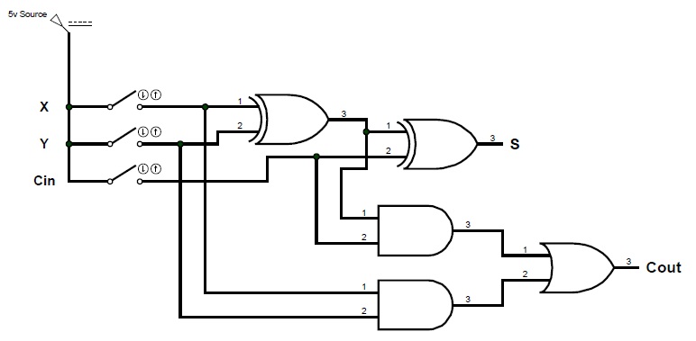
Full Adder Circuit: Theory, Truth Table & Construction

EDACafe: Power, accuracy and noise aspects in CMOS mixed-signal

Solved Build the Adder-Subtractor circuit from Page 18 from | Chegg.com

boolean - How to determine an Overflow in a 4 bit ripple-carry adder

Adders | CircuitVerse