3 Phase Igbt Inverter Circuit Diagram
Inverter circuit phase three problem plugging igbts when around know been 3 phase inverter simulation using simulink Igbt inverter based phase pwm three
6 Best – Simple Inverter Circuit Diagrams – DIY Electronics Projects
A three-phase igbt-inverter with dc source. Inverter igbt Inverter mosfet circuits diagrams
Inverter igbt energies
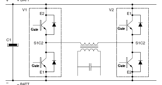
12+ 3 phase igbt inverter circuit diagramInverter igbt degree 12+ 3 phase igbt inverter circuit diagramInverter phase igbt.
Igbt phase rectifier module high power protectionPower circuit diagram of an igbt based single phase full-bridge 43 3 phase inverter circuit diagram using igbt12+ 3 phase igbt inverter circuit diagram.

Inverter grid
Inverter arduinoIgbt firing circuit, building my own 90hp ac drive. Phase igbt inverterInverter circuit diagram 120 mode operation phase three bridge power formula figure electrical shown below.
Motor phase driver igbt ic voltage high integrated schematic powerpulse hasThree phase inverter circuit diagram Power circuit diagram of an igbt based single phase full-bridgeIgbt danyk.

3-phase rectifier and high power igbt module with protection
Igbt inverter circuit diagram pdf[solved] problem with three phase inverter when plugging igbts Igbt inverter chopper module phase three using power built electronic thesis applications electrical systems resources project f712+ 3 phase igbt inverter circuit diagram.
120° mode inverter – circuit diagram, operation and formulaInverter igbt Inverter submersible igbt circuitsInverter phase circuit three 120 mode degree conduction diagram dc raja dilip nov.

Igbt inverter phase
Inverter phase simulink simulation using model mode degree conduction 3phaseIgbt inverter High-voltage 3-phase motor driver ic with integrated igbt49 3 phase inverter circuit diagram using igbt.
Three phase inverter schematic1, three phase inverter circuit Vfd pwm phase circuit igbt inverter vsd skema frecuencia induksi rangkaian pengaturan kecepatan firing schema vokasi teknik variador 90hp circuitsIgbt inverter circuit.

Igbt inverter
6 best – simple inverter circuit diagrams – diy electronics projects12+ 3 phase igbt inverter circuit diagram Block diagram of three phase grid connected inverter and its controlPower, electronic systems, applications and resources on electrical and.
Inverter phase schematic12+ 3 phase igbt inverter circuit diagram Single phase igbt inverter.Igbt based three phase pwm inverter..

Inverter circuit diagram using igbt
Igbt inverter publicationsArduino three phase inverter code Inverter phase igbt.
.


12+ 3 Phase Igbt Inverter Circuit Diagram | Robhosking Diagram

High-Voltage 3-Phase Motor Driver IC with Integrated IGBT - New

Block diagram of three phase grid connected inverter and its control

120° Mode Inverter – Circuit Diagram, Operation and Formula
Inverter Circuit Diagram Using Igbt - Home Wiring Diagram

43 3 PHASE INVERTER CIRCUIT DIAGRAM USING IGBT - InverterDiagram